Micrel, Inc.
MICRF112
December 2011
14
M9999-120911
(408) 944-0800
Application Information
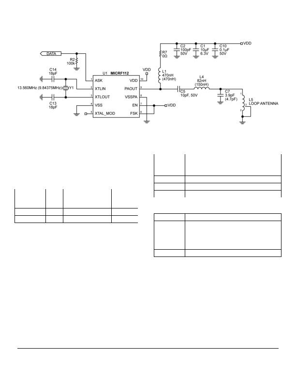
Figure 6. ASK 433.92MHz and 315MHz
Note: Values in parenthesis are for 315MHz
The MICRF112 is well suited to drive a 50 ohms source,
monopole or a loop antenna. Figure 6 is an example of a
loop antenna configuration. Figure 6 also shows both
315MHz and 433.92MHz ASK configurations for a loop
antenna. Besides using a different crystal, Table 1 lists
modified values needed for the listed frequencies.
Frequency
(MHz)
L1
(nH)
C5
(pF)
L4
(nH)
C7
(p
F)
Y1 (MHz)
315.0
470
10
150
6.8
9.84375
433.92
680
10
82
4.7
13.5600
Table 1
The reference design shown in Figure 6 has an antenna
optimized for using the matching network as described in
Table 1.
Power Control Using External Resistor
R7 is used to adjust the RF output levels which may be
needed to meet compliance. As an example, the
following tables list typical values of conducted RF
output levels and corresponding R7 resistor values for
the 50& test board shown in Figure 2. R7 of the TX112
Demo board using the loop antenna can be adjusted for
the appropriate radiated field allowed by FCC or ETSI
compliance. Contact Micrel for suggested values to meet
FCC and ETSI compliances.
R7, &
Output Power, dBm
IDD, mA
0
10
6.7
75
8.5
6.3
100
8.0
6.2
500
1.6
4.13
1000
-3.8
4.87
Output Power Versus External Resistor at 315MHz
R7, &
Output Power, dBm
IDD, mA
0
8.68
7.5
75
8.34
7.33
100
8.02
7.3
500
4.34
6.3
1000
0.42
5.5
Output Power Versus External Resistor at 433.92 MHz
发布紧急采购,3分钟左右您将得到回复。
相关PDF资料
MICRF405YML TR
TRANSMITTER ASK/FSK 24-MLF
MTX-102-433DR-B
MODULE TRANSMITTER 433MHZ 18DIP
MTX-103-915DR-B
MODULE TRANSMITTER 915MHZ 18DIP
MTX-405-433DR-B
MODULE TRANSMITTER 433MHZ 24DIP
N50P105
IC MODULE MINI JOYSTICK SMD
OCB350L187Z
BOARD CALIBR CIRCUIT OPB350L187
OMB.242.08F21
OMNI OUTDOOR ANTENNA
OMNILOG90200
ANTENNA ISOTRP 700MHZ-2.5GHZ RAD
相关代理商/技术参数
MICRF112YMM10
制造商:MICREL 制造商全称:Micrel Semiconductor 功能描述:QwikRadio? UHF ASK/FSK Transmitter
MICRF112YMU TR
功能描述:射频发射器 300MHz to 450MHz ASK/FSK Transmitter
RoHS:否 制造商:Micrel 类型:ASK Transmitter 封装 / 箱体:SOT-23-6 工作频率:300 MHz to 450 MHz 封装:Reel 工作电源电压: 最大工作温度: 安装风格:
MICRF112YMU-TR
功能描述:RF Transmitter ASK, FSK 300MHz ~ 450MHz 10dBm 50kbps PCB, Surface Mount Antenna 10-XFDFN Exposed Pad 制造商:microchip technology 系列:QwikRadio? 包装:剪切带(CT) 零件状态:停产 频率:300MHz ~ 450MHz 应用:RKE,TPM 调制或协议:ASK,FSK 数据速率(最大值):50kbps 功率 - 输出:10dBm 电流 - 传输:11mA 数据接口:PCB,表面贴装 天线连接器:PCB,表面贴装 存储容量:- 特性:- 电压 - 电源:1.8 V ~ 3.6 V 工作温度:-40°C ~ 125°C 封装/外壳:10-XFDFN 裸露焊盘 标准包装:1
MICRF113
制造商:MICREL 制造商全称:Micrel Semiconductor 功能描述:QwikRadio㈢ ASK Transmitter
MICRF113_11
制造商:MICREL 制造商全称:Micrel Semiconductor 功能描述:300MHz to 450MHz +10dBm ASK Transmitter in SOT23
MICRF113-315 EV
制造商:Micrel Inc 功能描述:evaluation board for MICRF113
MICRF113-315-EV
功能描述:EVAL BOARD FOR MICRF113 315MHZ 制造商:microchip technology 系列:QwikRadio? 零件状态:有效 类型:发射器 频率:315MHz 配套使用产品/相关产品:MICRF113 所含物品:板 标准包装:1
MICRF113-433 EV
制造商:Micrel Inc 功能描述:evaluation board for MICRF113